Custom designed here at Specialist Tooling Technologies Ltd
What our software can achieve
This software allows users to connect devices and create inspection recipes for guided inspection routines. The data is saved to an OBDC standard database compatible with Microsoft Access.
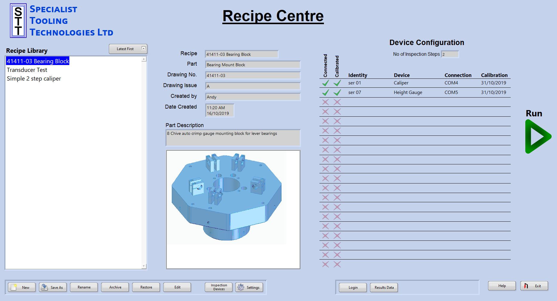
From the main screen operators can select a recipe to view the contents. The devices required by the recipe are listed on the right, they are checked to ensure they are in calibration and configured as ‘connected’. The operator then simply runs the recipe and follows the list of measurements.
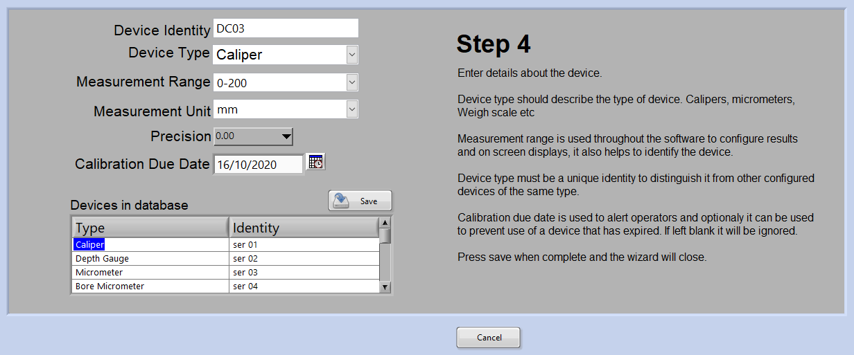
The wizard will attempt to first identify a newly created com port and then attempt to communicate using some standard settings and a range of usual commands. By entering the current reading in step 3 it can avoid picking up other data that may be included in the devices response.
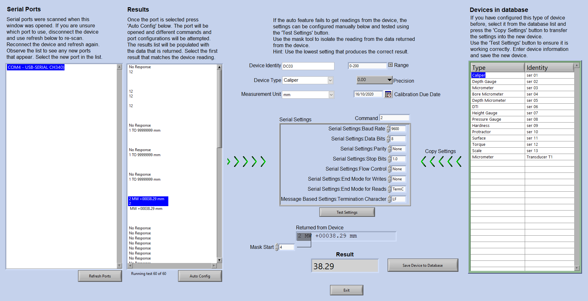
The manual option can also perform the same tests as the wizard but the settings can then be changed to find the right setting. If you know the settings for a device it can be faster to enter it here, perform a test and then store it in the database.
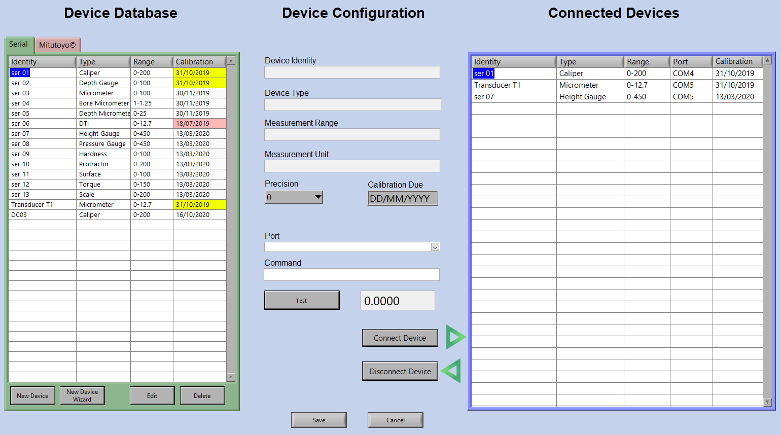
When devices are configured and stored they are not automatically set as ‘connected’. In the device management screen the two tabs on the left list all configured devices present in the databases. One tab for serial and another for Mitutoyo devices intended to connect directly to one of the dedicated ports.
The right hand table shows the devices currently ‘connected’. A device needs to be connected here before any recipe requiring it can be used. When the device is first configured the port and command are not stored because it may not be connected to the same port so it must be selected again at this stage.
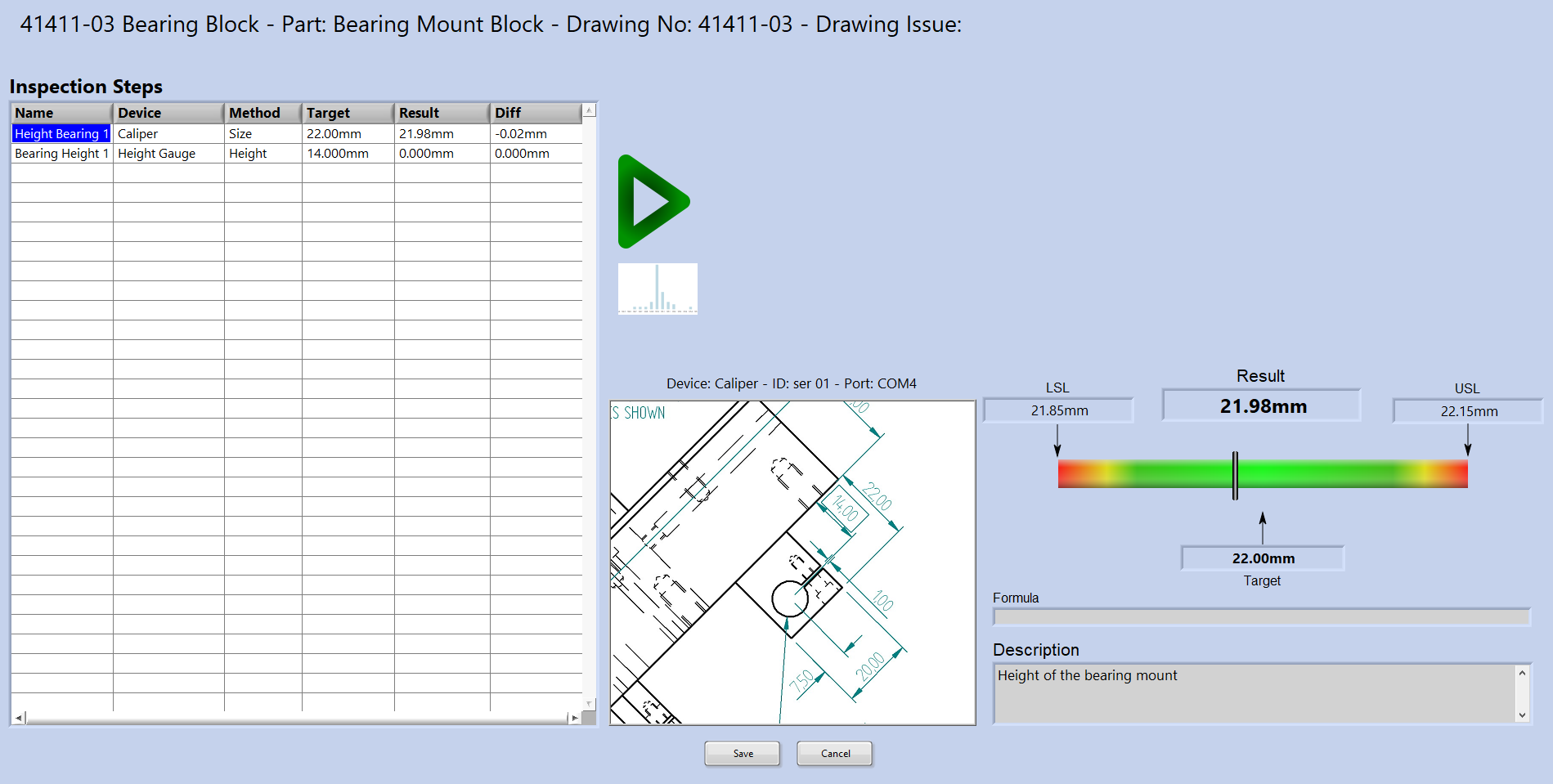
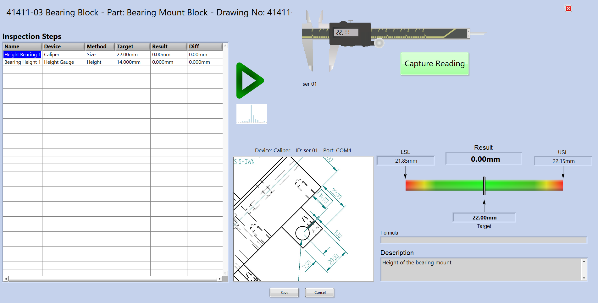
The run screen lists the measurement steps required, select a step to view the graphic showing the drawing snippet and the device required including the port it should be connected to. Press start (Green triangle) to begin reading the device live. The on-screen graphic updates as the device is operated. When ‘Capture Reading’ is pressed the system waits for a stable reading before returning the result.
The graphic shows clearly if the reading is within tolerance and writes the result to the table. Once all inspection steps are completed pressing save will write all the data to the measurement database.
The run screen lists the measurement steps required, select a step to view the graphic showing the drawing snippet and the device required including the port it should be connected to. Press start (Green triangle) to begin reading the device live. The on-screen graphic updates as the device is operated. When ‘Capture Reading’ is pressed the system waits for a stable reading before returning the result.
Recipes are simple to create with the editor.
A part image can be selected, this is displayed on the main screen when recipes are selected from the list.
Add a drawing image and this can be used to illustrate what the operator needs to measure. Only one drawing image per recipe is needed, snippets are created for each measurement step.
If a CSV file is selected then measurement steps can be created to extract data from that file every time it is updated. For example if a CMM is set to output results to a CSV file this recipe, when run, will monitor the CSV file and extract the results when it changes.
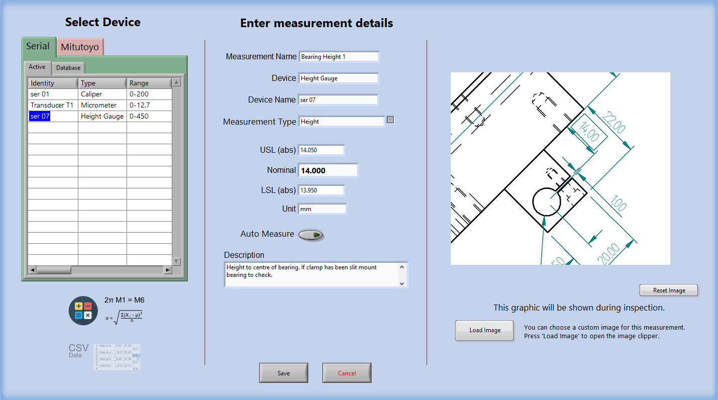
The measurement step editor has three main options:
• Get reading from a device • Calculate a result from other measures in the recipe • Monitor and extract data from a CSV file.
The devices tabs show all devices in the database and devices currently connected. Any may be selected to create the recipe. Each measure step configured for a device can use either a default graphic or a snippet from the drawing image configured in the recipe.